
Adding a fixed resistor ½ the value of a variable resistance sensor improves Arduino performance.
Whenever you connect a 2-lead variable resistor (VR) sensor (like a photo cell or bend sensor) to an Arduino, you add a resistor to it. I did this with my knitted stretch sensor. It creates a circuit known as a voltage divider, which controls the voltage level, based on the relative resistance of the resistor to the sensor. This is important because the voltage level is what AnalogRead "reads" in Arduino.

I wondered what value would give the best performance for my knitted sensors. So I used the equation below to calculate the output range of voltage dividers, based on the ratio between R1 and R2, given that R2 is my knitted sensor and R1 is the (unchanging) resistor. I graphed the outputs for each VR value at 0%, 25%, 50%, 75%, and 100% of its maximum range.

I found as I widened the ratio, the range widens; the bottom part gets steeper but the top flattens out.
I liked the results of a 1:2 ratio (light blue line) so I used that with my knitted sensors.
Later, I looked online and found Adafruit’s tutorial on photocells, which suggests using the Axel-Benz formula (choose a resistor the square root of the min + max resistance of your resistive sensor). This is useful if your minimum resistance isn’t zero. For my examples, it suggested a value slightly higher than the ½ value I’d settled on.
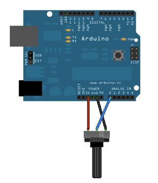
On a final note, none of this can match the range of a single potentiometer: when R2 decreases as R1 increases, we get a nice linear sweep with a full range from 0V to V+.

Lead 2 <--> Lead 3 = Resistor 2
But sometimes a pot just isn’t what you need.